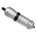
Coiled tubing has no pipe rams to close on it mid-string, so the barrier either travels with the string or is built into it. A dual-flapper check valve sits in the bottomhole assembly and gives the crew two independent flappers against reverse flow from the well. The lock-out sleeve is the second half of that idea: when the job calls for reverse circulation or a down-annulus squeeze, the sleeve shifts to hold both flappers open and the string stops behaving as a one-way valve.
How the Dual-flapper Check Valve Holds Two Barriers
Two flappers in series are not redundancy for its own sake. The upper flapper sits below the connector and the lower flapper sits above the catcher sub, so a failed seat or a failed hinge does not open the well. Each flapper closes on a machined seat and is held shut by spring force and by well pressure, and the assembly is rated to 10,000 psi working pressure. On a live well the argument for two barriers is the same as the argument for two BOP rams: an inspection interval that can be defended, and a single failure that does not become a well control event.
Setting the Lock-Out Sleeve
The sleeve is shifted by dropping a ball and applying pressure, which shears a pin and drives the sleeve down over both flappers. Once locked out, the flappers stay open and the string can reverse circulate to displace the well or spot a fluid. That is a deliberate loss of barrier, so the procedure has to state who authorises it, what the well condition is at the time, and how barriers are restored if the sleeve is not run back. On most interventions the sleeve is used for one circulation at the end of the job, not for the whole job.
Shear Values and the Pumping Schedule
The ball seat is chosen against the pumping schedule, because the shear value must sit above the pressure needed to move the fluid and below what the coiled tubing string and surface equipment can safely take. The crew works out hydrostatic and friction for the planned rate, adds margin for a cold string, and picks the seat from the chart. A seat that shears early wastes the run; a seat that never shears leaves a ball sitting on a locked string. Both outcomes are avoidable with arithmetic done before rig-up, and neither is worth discovering at the wellsite.
Threads and Sizes on the Dual-flapper Check Valve
The tool is built from 1.5 inches to 3.875 inches outside diameter, with inside diameters from 0.62 inches to 2.125 inches, so one barrier concept covers a slim workover string and a 2-7/8 inch completion. Connections include 1 inch AMMT, 1.5 inch AMMT, 2-3/8 inch PAC, 2-3/8 inch EUE and 2-7/8 inch EUE, which lets the valve make up directly to common coiled tubing connectors and to tubing on a through-tubing job. The catcher sub is integral rather than added below, which shortens the assembly and keeps the flappers close to the end of the string where reverse flow arrives first.
Testing Before It Goes in the Hole
Every assembly is pressure tested before it leaves the yard, and the test is repeated at the wellsite on the coiled tubing. The crew tests in both directions, against the flappers and past the lock-out sleeve, because a valve that holds from below and leaks from above fails the moment the job changes direction. Three records travel with the tool:
The yard test chart, signed and dated.
The ball seat size and the shear value as installed.
The make-up torque on each connection in the assembly.
None of those can be reconstructed at the wellsite, and all three are asked for when a job is reviewed afterwards. On a rig where the coiled tubing unit sits on a day rate, the test is the cheapest part of the work.
A dual-flapper check valve gives a coiled tubing string a barrier it can carry, and the lock-out sleeve gives the crew a controlled way to set that barrier aside for a circulation. Both halves only work when the shear value, the threads and the test chart are right before the string goes in the hole.
For more information, please contact China Vigor at info@vigorpetroleum.com or call +0086 29 81161513.