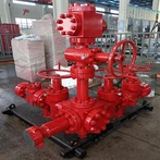
Coiled tubing intervention creates a demanding connection environment. The continuous string is reeled, straightened, bent through the injector path, and exposed to axial load, pressure, fatigue, and treatment fluids. China Vigor's Vigor External Slip Connector is a coiled tubing tool for connecting the string to a downhole assembly. Its value should be assessed through load transfer and operational control: it must grip the tube without unacceptable local damage, retain the required pressure boundary, and provide a documented interface to the BHA. Current product documentation and a well-specific engineering review must establish actual dimensions, materials, torque, pressure ratings, and pull limits.
External Slips Transfer Tensile Load
An external slip connector generally uses gripping segments around the coiled-tubing outside diameter. Under tension, slip geometry is intended to increase mechanical engagement with the tube surface. This is different from a conventional threaded joint because the connection is made around continuous tubing. Depending on the configuration, the assembly may include a mandrel, cone, slips, retaining parts, seals, and a crossover suited to the selected bottomhole assembly.
Tube condition is central to the decision. Wall thickness, ovality, corrosion, mechanical damage, and accumulated fatigue affect available load capacity. A connector is not a means of restoring damaged tubing to its original strength. The intervention engineer should use the latest inspection records and installation procedure to determine whether the proposed connection location is acceptable.
Preparation Controls Repeatability
Preparation starts by confirming tubing outside diameter, nominal wall, material grade, and service history. The connection area should be cleaned and inspected under the approved procedure. Correct cut quality and end preparation help the slips and seals seat as intended. Installation normally includes controlled make-up, dimensional verification, and confirmation that external components are fully engaged before pressure is applied.
A practical checklist includes:
Confirm tubing size, wall thickness, inspection status, and the planned connector configuration.
Verify BHA weight, expected overpull, pump pressure, well temperature, fluid chemistry, and pressure-control equipment.
The envelope should cover both static and dynamic forces. A string traveling through a 30-degree build section or a long horizontal interval can see force changes not evident from surface tension alone. The magnitude is well-specific and should be modeled using the approved coiled-tubing force analysis.
Mechanical Retention and Sealing Differ
Connection integrity has two related but distinct elements: mechanical retention and pressure containment. A pull test does not by itself prove a pressure seal, and a pressure test does not replace confirmation of correct slip engagement. The program should state the test medium, maximum test pressure, hold time, and allowable pressure loss. Units must remain consistent across the BHA drawing, pressure-control plan, and field record.
For context, a plan may use distinct verification steps at 1,000 psi, 3,000 psi, or 5,000 psi only when those values are within the approved equipment envelope. They are examples of planning notation, not ratings for the Vigor External Slip Connector. A 30-minute hold or a 60-minute hold may likewise be a procedure-specific requirement, not a universal test rule.
Fluid and Temperature Compatibility
Coiled-tubing operations may involve nitrogen, brine, acid, solvents, or other approved fluids. Metals and seals need compatibility review for the intended service. Where the operation expects temperatures above 100°C or a 6 hours exposure, the design basis should use documented material data for the actual fluid system. No connector rating should be inferred from a general tool category.
Integration With the BHA
The connector is an interface between tools above and below it. The BHA may contain a check valve, disconnect, circulating sub, nozzle, motor, cleanout tool, or logging equipment. Crossover connection, overall length, and maximum outside diameter can influence access through restrictions and compatibility with the next component. All interfaces should be checked against the latest drawing revision.
Real-time monitoring of surface weight, pump pressure, returns, and injector behavior helps keep the job within planned limits. Unexpected changes should be assessed through the operating procedure rather than normalized because the connector is not visible at surface. China Vigor can provide technical documentation for the Vigor External Slip Connector; the completed job design should define approved installation, pressure testing, and load criteria.
*For Vigor External Slip Connector technical information, contact China Vigor at info@vigorpetroleum.com or +86 28 81161513.*